Specialist Task Force 603:
Measurement campaign to confirm simulation parameters to define Urban Rail ITS protected zones in 5915-5925 MHz
Who we are:
| Team leader:
|
|
| Team Members:
|
- Fabian de Ponte Müller, DLR, fabian.pontemueller@dlr.de
- Sravan Machiraju, NavCert, sravan.machiraju@navcert.de
- Friedbert Berens, FBConsulting, friedbert.berens@me.com
- Andreas Kwoczek, Andreas Kwoczek, andreas.kwoczek@t-online.de
- Sébastien Grimoud, RATP, sebastien.grimoud@ratp.fr
- Daniel Maaz, Siemens Mobility SAS, daniel.maaz@siemens.com
|
What we do
We are working in parallel on the following tasks: identification of sites in cities to perform field strength measurements, define different scenarios for measurements, specify test set-up with measurement process for each scenario.
When these three first tasks will be completed, we will perform field strength measurements with the specified scenarios and process on the selected sites and finally the measurement will be analysed.
For more details, see our Terms of Reference
Why we do it
ETSI Technical Report ETSI TR 103 580 v1.1.1 published in August 2019, proposes different methods to allow efficient sharing of the frequency band 5.9 GHz between Urban-Rail-ITS and Road-ITS and also concluded that complementary studies are required on the following tasks:
• Identify methods to define protected zones
• Define protected zone detection methods
• Define mitigation techniques to apply in protected zones
To define protected zone, propagation simulation has been performed to evaluate the level received by Urban-Rail-ITS base station and also train.
The TR 103 580 v1.1.1 has concluded that a measurement campaign will be needed to validate the propagation simulation results.
These results of the measurement campaign are expected in 2021 and will establish the baseline for the complementary studies on mitigation techniques aiming to update the current ETSI TR 103 580 under ETSI TC RT JTFIR.
How we do it
The STF is composed of the six following tasks:
T1 Identification of the relevant test cases
T2 Identification of the relevant areas to conduct the measurements
T3 Description of test procedures and test tools for each case
T4 Planning of the measurements
T5 Conduct the measurement campaign
T6 Conclusion of the measurement campaign, finalization and publication of the TR 103 704
The Task T1, T2 and T3 are the most critical ones due to tight time schedule. For efficiency, the workload will be shared among members of the STF in the most efficient way. There will be different main contributors for some tasks T1, T2 and T3 all there will be reviewer for all the tasks.
The TC RT and the TC ITS will both be involved in the consultation phase and approbation of deliverables process. This would be undertaken by the TC RT JTFIR.
The CEPT/ECC will be informed of the work progress.
The TC ERM will be informed by the TC RT JTFIR.
Tasks achievement
Task T1:
The task T1 has been completed with the identification of seven scenarios:
|
Scenario number
|
Definition
|
|
1
|
Parallel Tracks and Road at the same level
|
|
2
|
Parallel Tracks and Road with tracks on a viaduct
|
|
3
|
Parallel Tracks and Road with Road on a viaduct
|
|
4
|
Parallel Tracks and Road with Tracks entering in a tunnel
|
|
5
|
Crossing Tracks and Road with road on a bridge
|
|
6
|
Crossing Tracks and Road with tracks on a bridge
|
|
7
|
Isle (Group of vehicles) in a city or multiple RF sources
|
Task T2:
The Task T2 has been completed with the identification of the relevant areas to perform the measurements.
Measurements will take place on two RATP metro lines in Paris: line 6 and line 8. RATP line 6 corresponds to an Urban environment while RATP line 8 correspond to a suburban environment.
On RATP line 6, three sections have been identified:
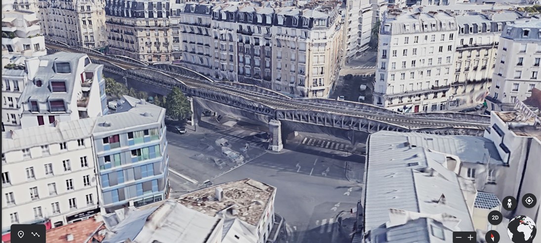
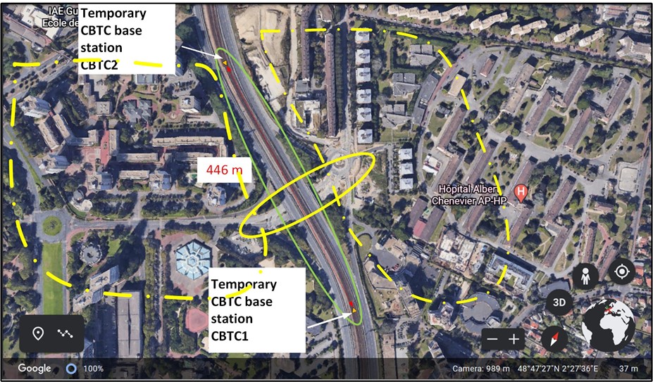
Section 1: From Station Duplex and Station Bir-Hakeim
In this section the tracks are on a viaduct.
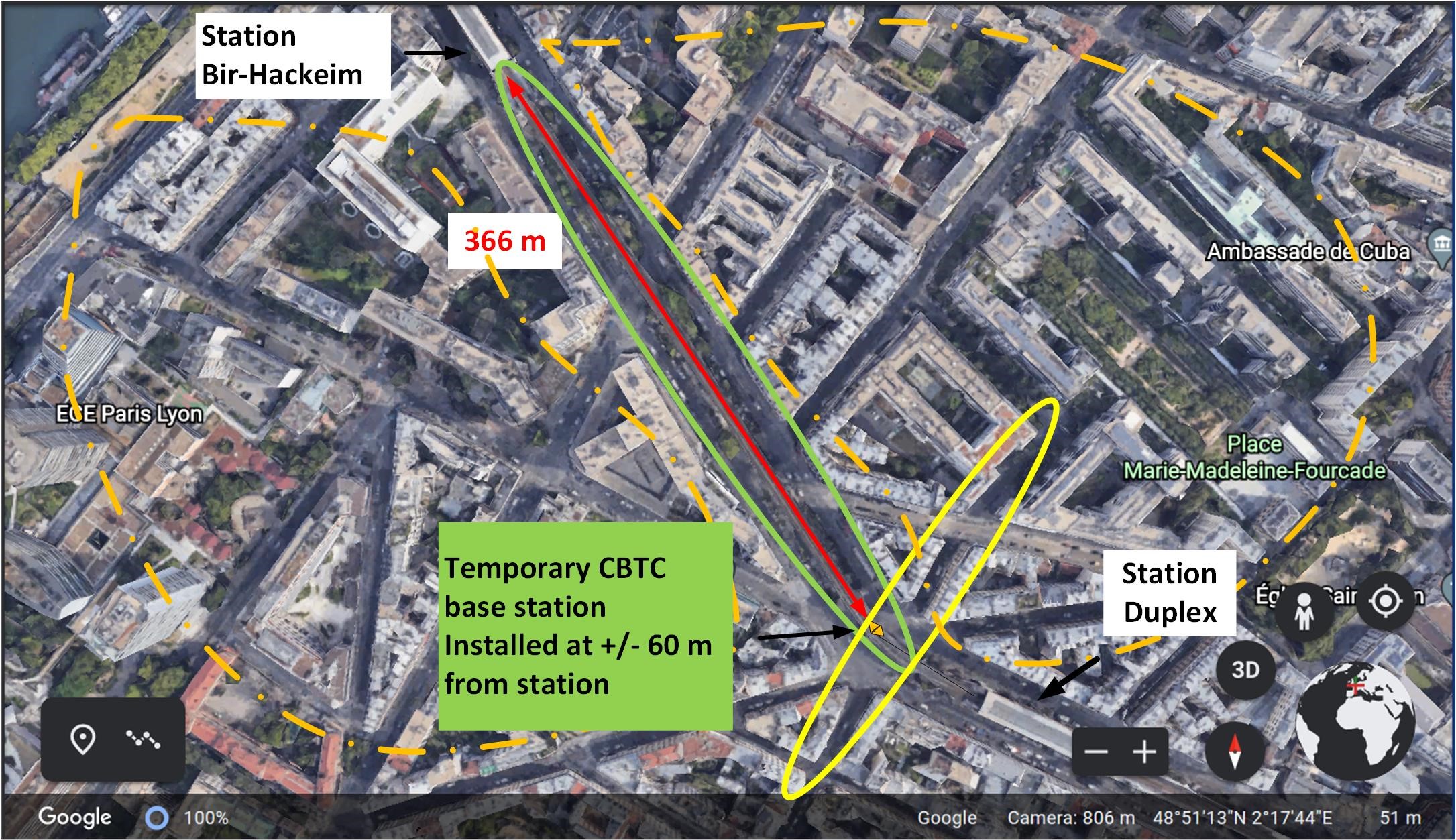
A temporary CBTC bas station will be installed in the curve at +/- 60 from the Duplex station extremity
The ellipse in green shows the area in which the train will be positioned for the measurements. The green ellipse encompasses also the two parallel roads, each one parallel to a side of the tracks on the viaduct.
The ellipse in yellow encompasses a road that cross the tracks. The transmissions of the vehicles running on this road will be received by a CBTC base station installed on the viaduct at the end of the curve and a train leaving the station Duplex.
In the area of the city surrounded by a line composed of a motif dot followed by a dash, the vehicles will circulate to measure the field-strength received from streets in the vicinity of the tracks.
Section 2: From Station Sèvres-Lecourbe and entrance of tunnel direction station Pasteur
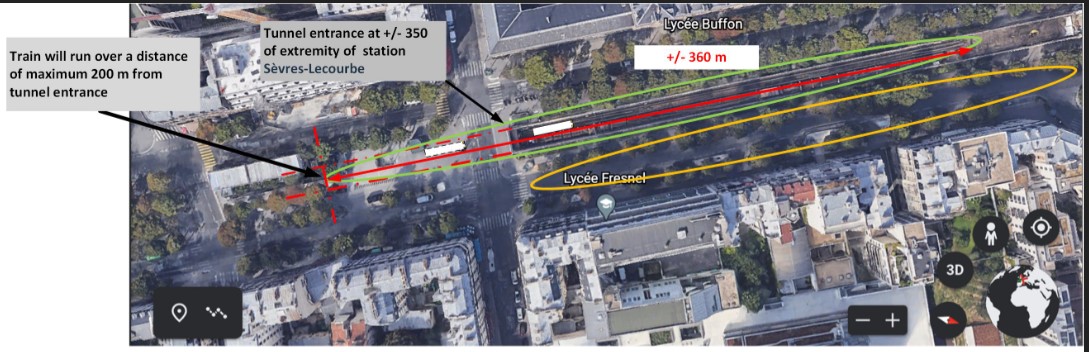
Two types of measurements will be performed with the train running in the tunnel and the train located at defined positions outside the tunnel.
For the first type of the measurements, the vehicles for measurements will be positioned at different locations on the road parallel to the tracks. For each vehicle position, the train will run over 200 m from the tunnel entrance to this one.
The objective of this type of measurements is to evaluate how far the vehicle transmissions penetrate inside the tunnel.
For the second type of measurements, the train will be positioned at defined location outside the tunnel and the vehicles for measurements will run on the road parallel to the tracks
Section 3: From Station Quai de la gare and entrance of tunnel direction Station Berçy
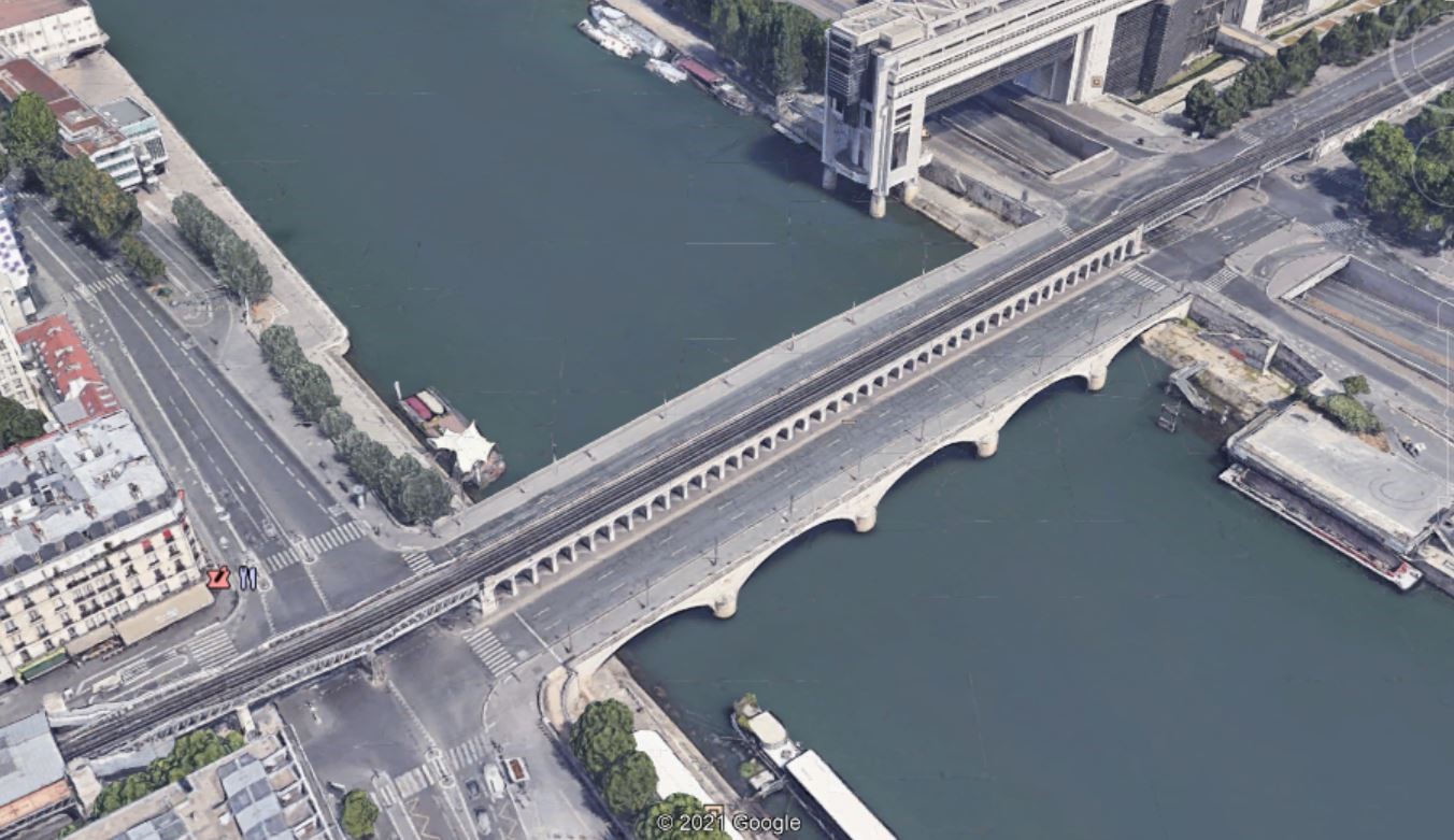
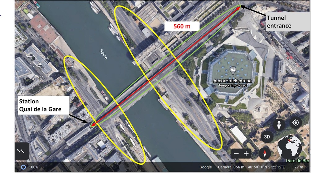
The ellipse in yellow encompasses the section of roads that a part of the circuit followed by the vehicles for measurements.
The two vehicles for measurements will run along on the bridge, on the roads surrounded by the yellow ellipse but not only.
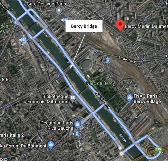
The measurements will be performed with two vehicles following a circuit that will include adjacent bridges as shown on the next figure.
On RATP line 8, three sections have been identified:
Section 1: Between depot of line 8 and the Station Pointe du Lac
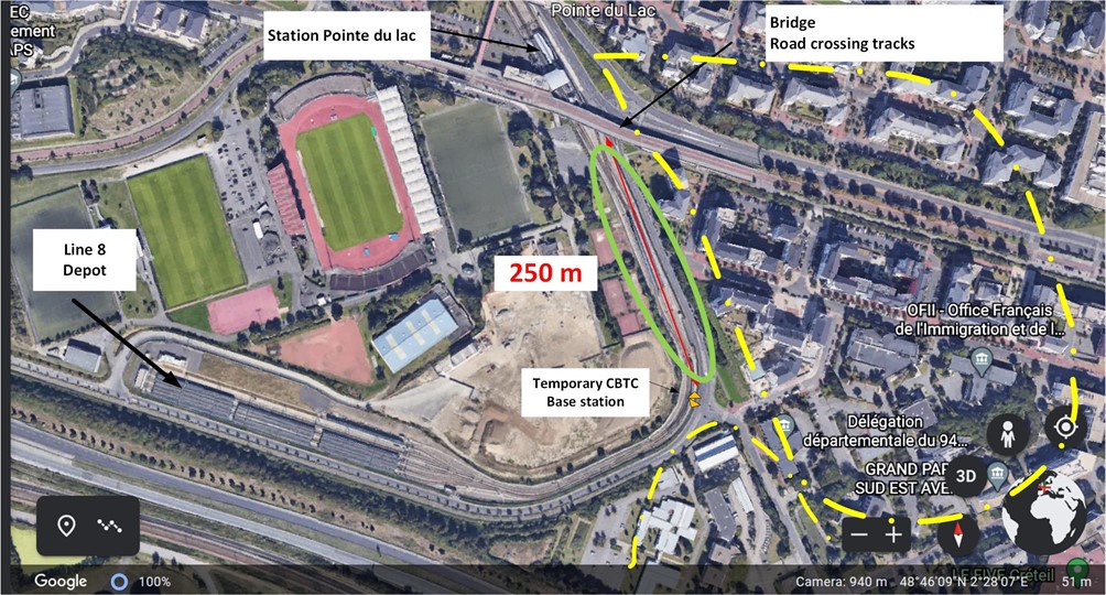
A temporary CBTC Base station will be installed at the end of the second curve of the depot with one antenna pointing to the station pointe du lac and the other one pointing to the track going to the direction of the depot.
For the measurements, the train will be positioned on section of the tracks surrounded by the green ellipse. This one encompasses also the parallel road on which the two vehicles for measurements will drive.
The two vehicles for measurements will drive on the parallel road to the track but not only. They will follow a circuit that includes the parallel road to the tracks and roads and streets around the metro line that are surrounded by a line composed of a motif dot followed by a dash.
Section 2: Between Station Créteil-Préfecture and Station Créteil-université.
The section starts at the extremity of Station Créteil and at ends at around 500 m from this one.
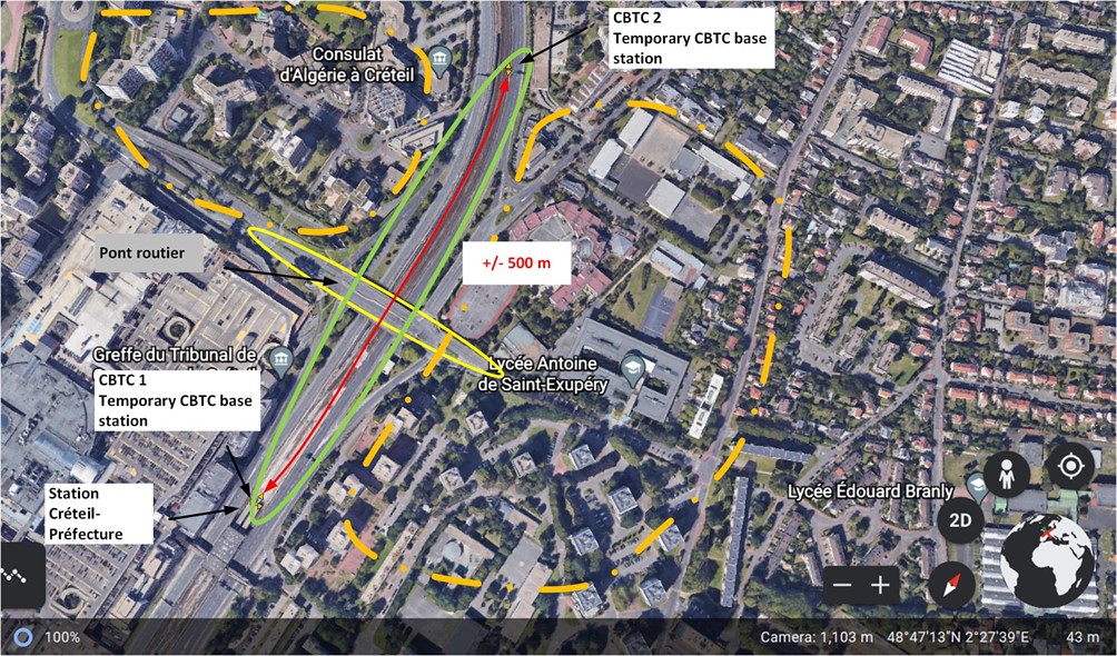
Two temporary CBTC base station will be installed.
For the measurements, the train will be positioned at different locations on the section of the tracks surrounded by the green ellipse. This one encompasses also the parallel roads on which the two vehicles for measurements will drive.
The yellow ellipse encompasses the bridge and the access to this one on which the vehicles will drive.
The two vehicles for measurements will drive on the parallel roads to the tracks but not only. They will follow a circuit that includes the parallel roads to the tracks, the bridge and roads and streets around the metro line that are surrounded by a line composed of a motif dot followed by a dash.
Section 3: Between Station Créteil-Préfeture and Station Créteil-université The section starts at around 616 meters from the extremity of Station Créteil-and ends at distance of around 1062 m from this one.
The section 3 of RATP line 8 surrounded by two parallel roads. Each road has two lanes.
The measurements will be performed with the train positioned at different locations on the section of the tracks surrounded by the green ellipse.
The two vehicles for the measurement will also drive on the two parallel roads surrounded by the green ellipse but not only.
The yellow ellipse surrounds a road crossing the tracks. The Tracks are on the bridge.
The two vehicles for measurements will drive on circuits that will include the two parallel roads, a passage below the bridge and the road and streets that are surrounded with a yellow line composed of a motif dot followed by a dash.
Task T3:
The Task T3 has been completed with the description of the test set-up and test procedures.
Test set-up:
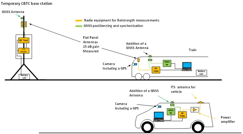
Generic measurement procedure:
1.The train is positioned at the first defined location
2.The RF measurement tool inside the train, inside the two vehicles and inside the temporary CBTC base stations via remote control are activated.
The RF measurement tool inside two vehicles are generating and transmitting test packets at a minimum frequency of 100 Hz.
The RF measurements inside the train and inside the CBTC base station are configured to receive the packets transmitted by the vehicles and records the level associated with a time stamp.
Inside the train and the vehicles, the messages issued by the GNSS receiver are recorded.
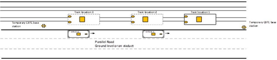
3.The two vehicles start driving on a defined circuit that will include parallel roads, bridge crossing the tracks and road and streets around the section of the metro line.
4.When both vehicles terminate their circuits, the recording of measurements are stopped and saved for each RF measurement tool and for the laptops PCs that record messages issued from GNSS receiver. File a stored with a name that identified clearly the measurements with date and an Identification Code related to the line and the relevant area.
5.The Train is positioned at the second defined location and the process is repeated from step 2.
Example of procedure:
Task T4:
The Task T4 is ongoing with the definition of the onsite planning.
Task T5:
The Task T5 is the measurement campaign. This one has started with test in laboratory.
Task T6:
Will be started after the measurements performed on site.
Deliverables
The STF 603 will provide the following deliverable:
• TR 103 704 is the main deliverable
• In addition, the following reports and draft will be issued:
o Progress report#1
o Interim Report 1 to the EC/EFTA (including the planification of the measurements) to be made available and approved by ETSI Secretariat
o Early Draft of the TR 103 704 made available to TC RT JTFIR, RT & ITS
o Interim Report 2 to the EC/EFTA (including a first feed-back of the different measures, the progress of each one, their success or not regarding the procedures expected) to be made available and approved by ETSI Secretariat
o Stable Draft of TR 103 704 made available to TC RT JTFIR, RT & ITS
o Final Draft of TR 103 704 approved by TC RT JTFIR, RT & ITS and published
o Final report to the EC/EFTA to be made available and approved by ETSI Secretariat
Time plan
| Destination
|
Description
|
Date
|
| ETSI
|
Progress report#1 approved by TC RT JTFIR, RT & ITS
Report on the Tasks T1, T2 & T3
|
28/02/2021
|
| EC/EFTA
|
Interim Report 1 to the EC/EFTA
Early Draft of the TR 103 704 made available to TC RT JTFIR, RT & ITS
|
30/04/2021
|
| EC/EFTA
|
Interim Report 2 to the EC/ Stable Draft of TR 103 704 made available to TC RT JTFIR, RT & ITS
|
31/08/2021
|
| EC/EFTA
|
Final Draft of TR 103 704 approved by TC RT JTFIR, RT & ITS and published
Final report to the EC/EFTA to be made available and approved by ETSI Secretariat
|
31/01/2022
|
To contact us, please send an e_mail to the stf603@group.etsi.org